Email
WhatsApp


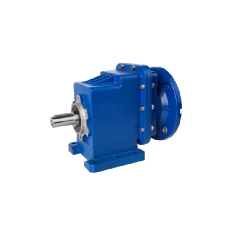
Picture this: you are standing in a plant maintenance aisle, a replacement PC Helical Gearbox has just arrived, and the installation team asks a direct question—how do I calculate the output torque of a PC helical gearbox? If you pause for a moment, you are not alone. Many procurement engineers and maintenance buyers face the same challenge because torque is not always printed as a simple number on the nameplate. Instead, it depends on motor torque, gear ratio, gear efficiency, and the real load the application demands. A wrong calculation can mean an undersized gearbox that runs hot, a frame that fails after only months, or a purchase that looks cheap but costs much more in downtime. This guide translates the calculation into a clear, practical process you can use before you sign the purchase order. You will learn the core formula, the variables that change the result, a real calculation example, the most common mistakes to avoid, and how Raydafon Technology Group Co.,Limited helps buyers turn torque data into a reliable selection decision. Use this guide as your fast field manual for verifying PC helical gearbox output torque instead of relying on guesswork.
In this article:
Imagine reviewing a supplier datasheet and seeing two torque values: rated torque and maximum torque. Which one should you use? If you pick the wrong number, the gearbox may pass a lab test but fail on the conveyor, mixer, or crane where it actually works. The solution is to separate available output torque from required output torque.
For a PC helical gearbox, the core formula is:
T_out = T_motor × i × η
This means the output torque T_out equals the motor input torque T_motor multiplied by the gear ratio i and the gearbox efficiency η. If you only know motor power and speed, first calculate motor torque with:
T_motor = 9550 × P / n
Here P is motor power in kW and n is motor speed in rpm. Then compare the available output torque with the application requirement multiplied by a service factor: T_required = T_load × S_f. The selection is safe when available torque is equal to or greater than required torque.
| Symbol | Meaning | Typical unit |
|---|---|---|
| T_out | Available output torque | Nm |
| T_load | Torque required by the application | Nm |
| S_f | Service factor | Dimensionless |
| i | Gear ratio | Dimensionless |
| η | Gearbox efficiency | Percentage |
| P | Motor power | kW |
| n | Motor speed | rpm |
Two identical-looking PC helical gearboxes can deliver different output torque because internal losses, ratio, and application conditions are not the same. A buyer who ignores efficiency or service factor often selects a unit that works on paper but struggles under start-stop duty or shock loading.
The solution is to collect four numbers before running the calculation: gear ratio, gearbox efficiency, service factor, and the continuous load torque at the output shaft. Raydafon Technology Group Co.,Limited publishes these values for each PC helical gearbox model, so you do not have to assume a generic efficiency number.
| Parameter | Why it matters | How Raydafon helps |
|---|---|---|
| Helical gear efficiency | Meshing, bearings, and seals create losses | Provides rated efficiency per model |
| Gear ratio | Multiplies input torque to the output shaft | Exact ratio shown on datasheet |
| Service factor | Accounts for shock, starts, and hours | Application guide suggests suitable S_f |
| Thermal rating | Continuous duty can limit allowable torque | Confirms performance against duty cycle |
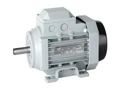
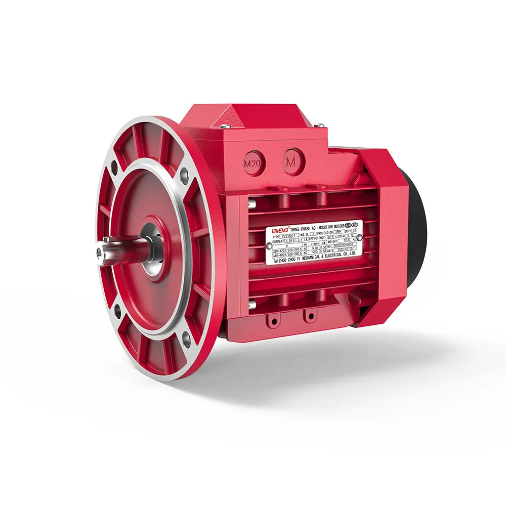
Let us walk through a common plant scenario. A conveyor needs 420 Nm of continuous torque at the output shaft. The drive motor is 5.5 kW at 1450 rpm, the PC helical gearbox ratio is 20:1, catalog efficiency is 94%, and the application requires a service factor of 1.25.
First calculate motor input torque:
T_motor = 9550 × 5.5 / 1450 = 36.2 Nm
Then calculate available output torque:
T_out = 36.2 × 20 × 0.94 = 680.6 Nm
Now calculate the required output torque including service factor:
T_required = 420 × 1.25 = 525 Nm
Compare the two values: 680.6 Nm available is greater than 525 Nm required, so the selection passes. If the available torque were lower, you would move to the next larger frame size or reduce the service factor only after a full application review.
| Input | Value |
|---|---|
| Motor power | 5.5 kW |
| Motor speed | 1450 rpm |
| Gear ratio | 20:1 |
| Gearbox efficiency | 94% |
| Available output torque | 680.6 Nm |
| Required output torque | 525 Nm |
| Result | Pass |
A common scene in procurement is the rush to match a replacement gearbox only by frame size. The physical dimensions fit, but the torque calculation does not, and the new unit fails after a few months. This often happens because the buyer uses the gearbox catalog maximum torque instead of the continuous torque required by the load.
The solution is to check every number before issuing the order. Use the actual load at operating speed, not the motor peak torque. Apply the correct service factor for shock and starts. Convert all units to Nm or lb-ft consistently, and remember that helical gear stages lose efficiency through heat and friction.
| Mistake | Why it happens | Fix |
|---|---|---|
| Using only rated torque | Datasheet values look safe but ignore load variation | Compare with load torque × service factor |
| Forgetting efficiency | Assumes 100% power transfer | Use catalog η for each gear stage |
| No service factor | Conveyors or mixers see shock loads | Apply 1.25 to 1.75 for typical duty |
| Ignoring output speed | Power changes with speed | Convert rpm before using power formula |
Q1: How do I calculate the output torque of a PC helical gearbox if I only know the motor power and output speed?
Start by finding motor input torque with T_motor = 9550 × P / n_motor, where P is motor power in kW and n_motor is motor input speed in rpm. Then multiply by the exact gear ratio and the gearbox efficiency: T_out = T_motor × i × η. After that, compare the result with the application load torque multiplied by the service factor. Raydafon Technology Group Co.,Limited can provide a rated torque chart for the exact model, which reduces the chance of conversion errors.
Q2: How do I calculate the output torque of a PC helical gearbox for a high-inertia conveyor with frequent starts?
Use the continuous load torque at the output shaft, not the motor peak torque, and then apply a higher service factor, usually 1.5 to 2.0 for frequent starts or heavy shock. If the available torque after ratio and efficiency is lower than the required torque, select the next larger frame size. For high-inertia loads, also check the gearbox thermal rating because repeated acceleration can generate more heat. Raydafon sales engineers can review acceleration time and load inertia to recommend a safe model instead of leaving the buyer to guess.
The calculation itself is simple, but the inputs are where buyers lose confidence. Incorrect ratio data, missing efficiency values, or a poorly chosen service factor can turn a standard replacement into a repeated failure. Raydafon Technology Group Co.,Limited removes that uncertainty by providing clear, model-specific technical data and application support for PC helical gearboxes.
| Selection requirement | Raydafon support |
|---|---|
| Accurate ratio and efficiency data | Published per model, not just generic ranges |
| Application-specific service factor | Sales engineers help match load type and duty |
| Pre-calculated output torque tables | Fast shortlisting for busy buyers |
| Custom shaft or flange options | Fits existing installation without redesign |
Before you finalize a PC helical gearbox purchase, confirm that you have the motor power, motor speed, gear ratio, efficiency, service factor, and continuous output torque requirement. Run the formula, compare available torque against required torque, and check the thermal rating for longer duty cycles. If any number is missing, request it from the manufacturer instead of estimating.
For reliable technical data and application support, contact Raydafon Technology Group Co.,Limited. The team helps procurement engineers and maintenance buyers verify PC helical gearbox torque calculations, compare frame sizes, and select a drive that fits both the mechanical and commercial requirements of the project. Send your motor data, output speed, load torque, and duty cycle to [email protected] for a quick selection review. A short calculation check today can prevent a costly line stoppage tomorrow.
Anderson, N.E., Loewenthal, S.H., 1980. Efficiency of nonstandard and high contact ratio involute spur gears. Journal of Mechanical Design, 102(1), 202-207.
Baglioni, S., Cianetti, F., Landi, L., 2012. Influence of the addendum modification on spur gear efficiency. Mechanism and Machine Theory, 49, 216-233.
Hohn, B.R., Michaelis, K., 2004. Influence of oil temperature on gear failures. Tribology International, 37(2), 103-109.
Kahraman, A., 1993. Effect of axial vibrations on the dynamics of a helical gear pair. Journal of Vibration and Acoustics, 115(1), 33-39.
Velex, P., Maatar, M., 1996. A mathematical model for analyzing the influence of shape deviations and mounting errors on gear dynamic behaviour. Journal of Sound and Vibration, 191(5), 629-660.
Kubur, M., Kahraman, A., Zini, D.M., Kienzle, K., 2004. Dynamic analysis of a multi-shaft helical gear transmission by finite elements: model and experiment. Journal of Mechanical Design, 126(3), 398-406.
Xu, H., Kahraman, A., Anderson, N.E., Maddock, D.G., 2007. Prediction of mechanical efficiency of parallel-axis gear pairs. Journal of Mechanical Design, 129(1), 58-68.
Jelaska, D., 1997. On the calculation of load capacity of spur and helical gears. International Journal of Mechanical Sciences, 39(3), 275-291.
Miler, D., Hoić, M., 2018. Optimisation of cylindrical gear pair efficiency. Transactions of FAMENA, 42(3), 41-50.
Radzevich, S.P., 2016. Theory of Gearing: Kinematics, Geometry, and Synthesis. Mechanism and Machine Theory, 105, 1-15.
-