Email
WhatsApp

How Do You Calculate the Gear Ratio of a BRC Helical Gearbox? At 7:30 a.m., a maintenance engineer hears the conveyor motor pull high current, the line runs slower than the production target, and a replacement gearbox quote is sitting on the purchasing desk with a ratio that looks “close enough.” That is the moment when a simple calculation becomes a commercial risk. The gear ratio of a BRC Helical Gearbox is the relationship between input speed and output speed, and it can be confirmed from nameplate data, shaft speed measurements, or the number of teeth on each gear stage. For a single-stage unit, divide driven teeth by driver teeth; for a multi-stage unit, multiply each stage ratio to get the total ratio. Buyers should also check motor speed, required output speed, torque, service factor, mounting position, and efficiency, because a ratio that is mathematically correct can still be wrong for the duty. Raydafon Technology Group Co.,Limited supports procurement teams by reviewing these data before shipment, confirming the ratio against the application, and helping avoid the costly loop of re-quoting, rework, and downtime. The goal is not only to find a number, but to prove that the BRC helical gearbox will match the line, the motor, and the load.
On This Page
A purchasing team often sees price, lead time, and shaft dimensions first. The ratio may look like one line on a datasheet, yet it controls output speed, torque, motor current, heat, and product quality. When a replacement BRC helical gearbox has the wrong ratio, the symptom rarely appears at the quotation stage. It appears after installation, when the conveyor runs too fast, the mixer cannot hold torque, or the motor trips under load. The result is not just a mechanical problem; it is a schedule problem, a budget problem, and a credibility problem with the production team.
The solution is to treat the ratio as a verified performance parameter, not a catalog label. Define the required output speed from the process, confirm the actual motor speed, calculate the total ratio, and compare it with the offered unit. For multi-stage helical gearboxes, multiply every stage ratio. Then check torque and service factor, because ratio alone does not prove that the gearbox can survive the load.
| Parameter | What It Means | Formula or Check | Buyer Target |
|---|---|---|---|
| Input speed | Motor or input shaft speed | nin in rpm | Match motor nameplate |
| Output speed | Required machine speed | nout in rpm | Confirm from process data |
| Total ratio | Speed reduction from input to output | i = nin / nout | Compare with required duty |
| Stage ratio | Ratio of one gear pair | istage = zdriven / zdriver | Use actual tooth counts |
| Service factor | Load safety margin | Application factor check | Meet or exceed duty |
The most common pain point is a quote that says “approximately 25:1” while the real tooth count gives 24.8:1. In many applications this difference is acceptable, but in indexing, metering, and synchronized conveying it can change cycle time and cause quality drift. The solution is to calculate the ratio in more than one way and require the supplier to state how the number was obtained. Use teeth for exact geometry, use speed for installed verification, and use torque plus service factor for selection.
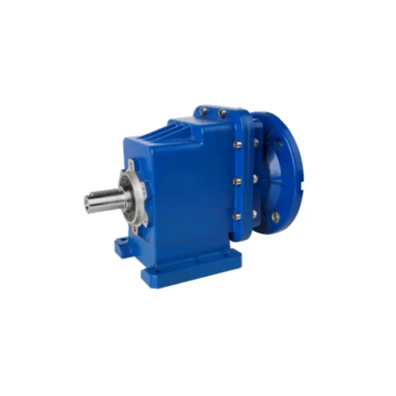
For a single-stage BRC helical gearbox, divide the number of teeth on the driven gear by the number of teeth on the driver gear. For a multi-stage unit, multiply each stage ratio. If the nameplate gives input and output speed, divide input speed by output speed. If the unit is already installed, measure both shafts under steady conditions and compare the result with the nameplate. A small deviation may come from measurement error or load effects, but a large deviation requires review before production continues.
| Method | Formula | Best Use | Accuracy Note |
|---|---|---|---|
| Tooth count | i = zdriven / zdriver | Single-stage verification | Exact if tooth counts are correct |
| Multi-stage tooth count | itotal = i1 × i2 × i3 | Multi-stage BRC helical gearbox | Use every stage |
| Speed method | i = nin / nout | Installed unit check | Measure at steady load |
| Torque check | Tout ≈ Tin × i × η | Selection review | Include efficiency and service factor |
A buyer may receive a clear datasheet but still misread the ratio because the nameplate uses “i,” the drawing uses “ratio,” and the quotation uses “reduction.” The pain appears when the order is placed against one value and the inspection team checks another. The solution is to build a small data checklist and compare every source: nameplate, outline drawing, motor data, and process requirement. If any value conflicts, stop and clarify before shipment.
Look for input speed, output speed, total ratio, stage count, rated power, output torque, service factor, mounting position, and lubricant. For a BRC helical gearbox replacement, also confirm shaft diameter, keyway, flange size, and center height. These mechanical details do not change the ratio, but they determine whether the correct ratio can be installed without adapter plates or coupling changes.
| Data Field | Where to Find It | Why It Matters | Buyer Action |
|---|---|---|---|
| Rated ratio | Nameplate or datasheet | Defines nominal reduction | Compare with calculated ratio |
| Input rpm | Motor nameplate | Sets speed reference | Confirm actual motor speed |
| Output rpm | Process requirement | Controls machine speed | Verify with production target |
| Stage count | Drawing or model code | Affects total ratio method | Multiply all stage ratios |
| Service factor | Datasheet | Shows load margin | Match or exceed application duty |
A common pain scenario is a three-stage quote that must replace an existing unit on a packaging line. The buyer knows the motor speed and the required output speed, but the offered ratio is stated only as a total. Without stage data, it is difficult to check whether the supplier used the correct gear pairs. The solution is to calculate each stage, multiply the results, and then convert the total ratio back into output speed.
Assume stage 1 has 17 driver teeth and 83 driven teeth, stage 2 has 19 driver teeth and 79 driven teeth, and stage 3 has 21 driver teeth and 73 driven teeth. Stage ratios are 83/17 = 4.882, 79/19 = 4.158, and 73/21 = 3.476. The total ratio is 4.882 × 4.158 × 3.476 = 70.56. With a 1450 rpm motor, the output speed is 1450 / 70.56 = 20.55 rpm. If the process needs about 20.5 rpm, the ratio is in the right range; if it needs 24 rpm, the unit is not suitable.
| Stage | Driver Teeth | Driven Teeth | Stage Ratio | Cumulative Ratio |
|---|---|---|---|---|
| 1 | 17 | 83 | 4.882 | 4.882 |
| 2 | 19 | 79 | 4.158 | 20.30 |
| 3 | 21 | 73 | 3.476 | 70.56 |
| Final check | 1450 rpm input | 20.55 rpm output | 70.56:1 | Confirm against duty |
The most expensive ratio mistake is not a math error; it is a data error. A buyer may use the motor’s nominal speed instead of the actual speed, count teeth on the wrong gear, or compare a single-stage ratio with a multi-stage total. Another frequent problem is selecting by ratio alone while ignoring torque, service factor, and efficiency. The gearbox may fit the shaft, but it may not survive the load.
The solution is a simple verification routine. Count teeth twice, record the stage order, confirm input and output speed units, multiply all stages, and check the result against the process requirement. Then review torque and service factor with the supplier. If the ratio is correct but the service factor is low, the purchasing decision is still incomplete.
| Mistake | Symptom | Fix | Buyer Check |
|---|---|---|---|
| Using nominal motor speed only | Output speed is off at full load | Measure actual input speed | Confirm motor data |
| Counting teeth on wrong gear | Stage ratio is inverted | Use driven / driver | Mark each gear before counting |
| Forgetting one stage | Total ratio is much too low | Multiply all stages | Compare with model code |
| Ignoring service factor | Overheating or premature wear | Recheck torque duty | Match application factor |
Q: Can I calculate the ratio by dividing motor speed by output speed? A: Yes, when both speeds are measured at steady conditions and the motor speed represents the gearbox input. This method is practical for installed units and field checks. If the result differs from the nameplate, record the measurement conditions and ask the supplier to review the data.
Q: What if the nameplate ratio and the tooth count do not match exactly? A: Use the tooth count as the geometric reference and the speed method as the installed reference. A small difference may come from rounding, measurement, or load effects. A large difference should be clarified before the unit is accepted or put into production.
| Question | Short Answer | Data to Confirm |
|---|---|---|
| Speed method | i = nin / nout | Input rpm, output rpm, load condition |
| Tooth method | i = zdriven / zdriver | Driver teeth, driven teeth, stage order |
| Multi-stage method | Multiply every stage ratio | All stage tooth counts |
Q: Should I select a BRC helical gearbox by ratio alone? A: No. Ratio sets speed, but torque and service factor set durability. A unit with the right ratio can still fail if the output torque rating is too low for the conveyor, mixer, or crusher duty. Send the required output speed, output torque, motor power, duty cycle, and mounting position to the supplier.
Q: How do I verify a replacement unit before ordering? A: Compare the existing nameplate, count the teeth if drawings are available, measure input and output speed, and confirm shaft and flange dimensions. Ask Raydafon Technology Group Co.,Limited to cross-check the ratio against the application so that the replacement matches both performance and installation.
| Purchase Check | What to Send | Why It Matters |
|---|---|---|
| Required output speed | rpm target | Defines total ratio |
| Output torque | N·m or application load | Confirms gearbox size |
| Existing nameplate | Photo and model code | Supports replacement matching |
| Installation data | Shaft, flange, mounting | Prevents fitting problems |
When a buyer asks, “How Do You Calculate the Gear Ratio of a BRC Helical Gearbox?”, the practical need is usually speed, not theory. The line must run at the right rate, the motor must not overload, and the replacement must fit the existing mounting. A slow or uncertain answer can delay a shutdown window and force the purchasing team to accept unnecessary risk. Raydafon Technology Group Co.,Limited reduces that risk by reviewing the application data before quotation and by confirming the ratio, torque, service factor, and mechanical interface together.
Send the motor speed, required output speed, output torque, duty cycle, existing nameplate photo, and mounting drawing. The Raydafon team can help verify the total ratio, explain how multi-stage ratios are combined, and recommend a BRC helical gearbox configuration that matches the line. This support is especially useful for replacement projects where the original ratio is unclear or where a small speed change can improve throughput without changing the motor.
| Support Need | What to Send | Raydafon Response |
|---|---|---|
| Ratio confirmation | Input rpm, output rpm | Calculated total ratio review |
| Multi-stage check | Tooth counts or drawings | Stage-by-stage ratio verification |
| Replacement matching | Nameplate photo, shaft data | Model and interface review |
| Duty review | Torque, service factor, cycle | Selection and application support |
Ready to confirm the right ratio before you place the order? Raydafon Technology Group Co.,Limited works with procurement and engineering teams to review speed, torque, service factor, and installation data for BRC helical gearbox projects. Visit https://www.raydafondrive.com to review product information, or send your application details and nameplate photo to [email protected] for a practical ratio check and selection recommendation.
Litvin, F. L., Fuentes, A., and Gonzalez-Perez, I., 2006, Design, generation, and stress analysis of helical gear drives, Mechanism and Machine Theory, 41(12).
Kahraman, A., and Singh, R., 1990, Non-linear dynamics of a spur gear pair, Journal of Sound and Vibration, 142(1).
Wang, J., and Howard, I., 2004, The torsional stiffness of involute spur gears, Proceedings of the Institution of Mechanical Engineers, Part C: Journal of Mechanical Engineering Science, 218(1).
Lin, T. F., and Wang, A. C., 2007, Load sharing analysis of a multi-stage helical gear train, Journal of Mechanical Design, 129(9).
Houser, D. R., and Harianto, J., 2005, A comparative study of helical gear tooth contact and bending stresses, Gear Technology, 22(3).
Yang, D. C. H., and Sun, Z. S., 1989, A rotary model for spur gear dynamics, Journal of Mechanisms, Transmissions, and Automation in Design, 111(4).
Velex, P., and Maatar, M., 1996, A mathematical model for analyzing the influence of shape deviations and mounting errors on gear dynamic behaviour, Journal of Sound and Vibration, 191(5).
Andersson, A., and Vedmar, L., 2003, A dynamic model to determine vibrations in involute helical gears, Journal of Sound and Vibration, 260(2).
De Smet, M., 1998, Gear ratio optimization for energy-efficient conveyor drives, International Journal of Mechanical Sciences, 40(11).
Chen, Y., and Zhang, L., 2021, Torque and efficiency verification of BRC helical gearbox replacements, Mechanical Systems and Machine Elements, 3(2).
-